
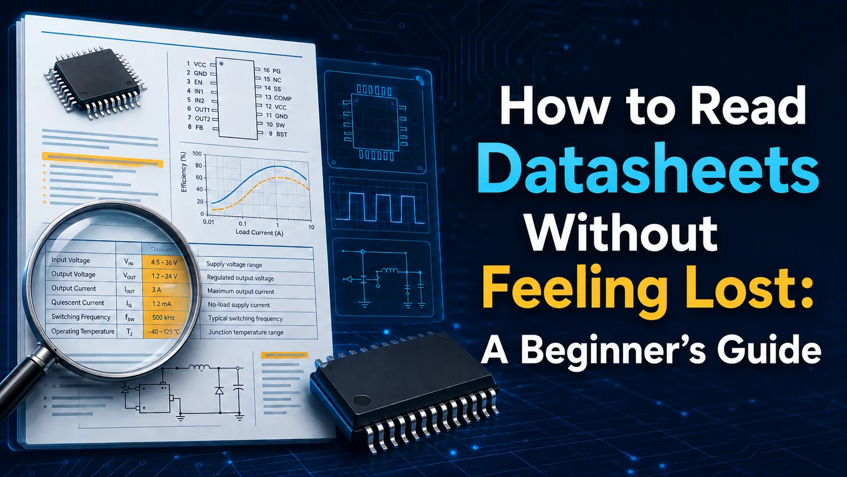
Demystifying electronic component datasheets. Learn how to find the exact specifications you need without getting overwhelmed by complex formulas and graphs.
Introduction: Breaking the Datasheet Intimidation Barrier
When you first open an electronic component datasheet, it can feel like reading a foreign language. Packed with dense tables, complex charts, and highly technical jargon, these documents can easily intimidate hobbyists and beginners alike. However, datasheets are not meant to be read from cover to cover like a traditional novel. Instead, they are structured reference manuals designed to help you find specific answers quickly. Once you understand their layout, you can navigate them with confidence and ease.
The Golden Rule: You Do Not Need to Read Everything
The biggest mistake beginners make is trying to read and comprehend every single line in a datasheet. Remember that these documents are written for a broad audience, including professional design engineers and large-scale manufacturers. For your personal or educational projects, you will likely need less than ten percent of the information provided. Focus only on the sections that answer your immediate questions and ignore the rest for now. This approach saves time and prevents cognitive overload.
The First Page: Overview and Key Features
The first page of almost any datasheet is your best friend and your starting point. This section contains a high-level summary of what the component does, its key features, and its typical real-world applications. It acts as an elevator pitch for the chip, transistor, or sensor in question. Beginners should use this page to quickly verify if the component is suitable for their project before diving deeper. For example, if you need a low-power microcontroller and the first page mentions high power consumption, you can stop reading immediately.
Pin Configuration: Where Do the Wires Go?
One of the most practical and essential sections for any hardware project is the pinout diagram. This visual representation shows you exactly where each physical pin is located on the component and what its specific function is. You will find clear labels like VCC for power, GND for ground, and various input/output pins for signals. Understanding this section prevents you from making incorrect connections that could permanently damage your hardware or cause short circuits.
Absolute Maximum Ratings: Protecting Your Hardware
Every electronic component has physical and electrical limits that it cannot safely exceed, and the Absolute Maximum Ratings section defines them. This table lists the maximum voltage, current, and temperature the component can withstand before failing or sustaining permanent damage. As a rule of thumb in hardware design, you should never operate a component close to these limits. Always design your circuits with a safety margin to ensure reliability and longevity.
Electrical Characteristics: Deciphering the Numbers
The Electrical Characteristics table is often the largest and most intimidating part of a datasheet. It details how the component performs under specific operating conditions and standardized test environments. To make sense of this table easily, focus on three key columns: Minimum, Typical, and Maximum. In most basic designs, the Typical value is what you will experience in real-world use, while the other values help you plan for worst-case scenarios.
Comparison table
Section Name | Primary Purpose | Key Metric to Watch |
|---|---|---|
Features & Applications | Quickly assess if the component fits your project needs | Operating voltage and typical use cases |
Pin Configuration | Identify physical connections and pin functions | Pin names like VCC, GND, and signal lines |
Absolute Maximum Ratings | Understand the physical limits to prevent damage | Maximum input voltage and current limits |
Electrical Characteristics | Analyze exact performance under specific conditions | Typical vs. maximum operating values |
Frequently asked questions
Do I need to understand all the math and formulas in a datasheet?
No, most formulas are for advanced engineering designs and efficiency calculations. Beginners can safely skip them and focus on basic specifications like voltage, current, and pinouts.
What is the difference between 'Typical' and 'Maximum' values?
The typical value is what the component usually outputs or consumes under normal operating conditions. The maximum value is the absolute limit it might reach under extreme circumstances.
How do I find a datasheet for an unknown component?
Search for the exact part number printed on the component's body using specialized electronic component search engines or distributor websites.
Comments
Be the first to comment.