
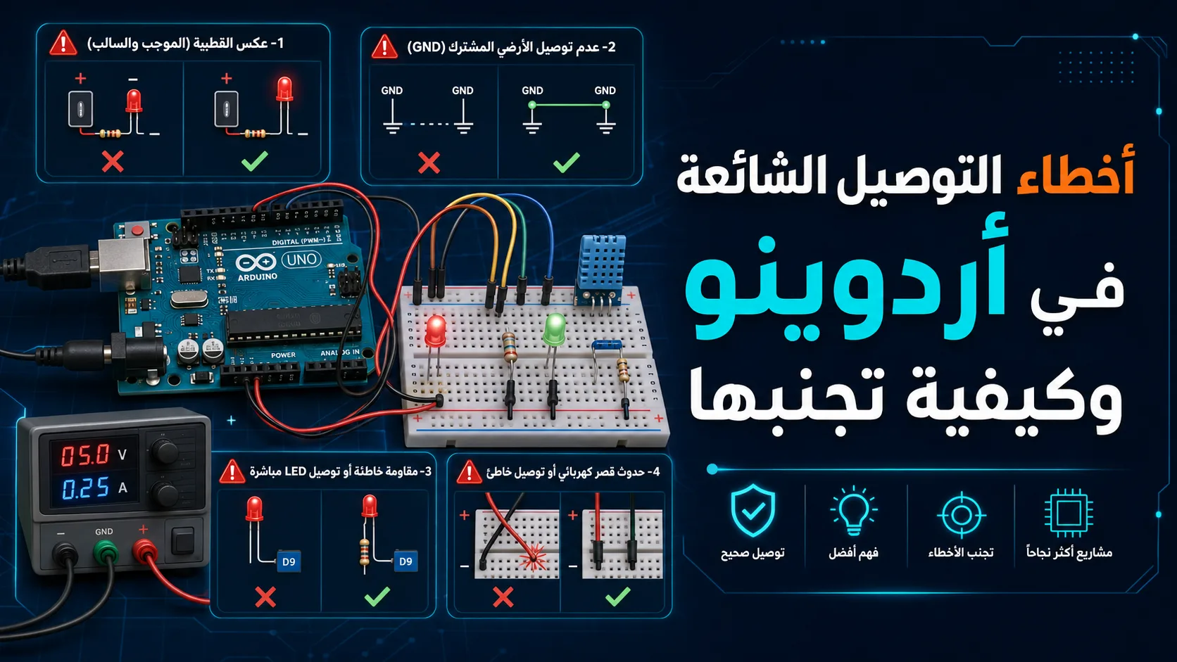
Learn how to identify and prevent the most common Arduino wiring mistakes, from short circuits to missing resistors, and keep your electronics projects running safely.
Introduction: The Excitement of Prototyping and Hardware Realities
Arduino has revolutionized the world of DIY electronics, making it accessible for hobbyists, students, and professionals to bring complex ideas to life. However, working with physical hardware introduces challenges that code alone cannot solve.
A single misplaced wire can lead to erratic behavior, damaged sensors, or even a completely destroyed microcontroller. Understanding basic electrical principles and how components interact with your board is essential for successful prototyping.
In this guide, we will explore the most common wiring mistakes made by makers, explain the science behind why they happen, and provide practical solutions to keep your hardware safe and functional.
Mistake 1: Connecting LEDs Without Current-Limiting Resistors
One of the most frequent mistakes made by beginners is connecting a Light Emitting Diode (LED) directly to an Arduino digital pin and ground. LEDs have very little internal resistance once they start conducting electricity.
Without a resistor to limit the current, the LED will attempt to draw as much current as the power source can deliver. This results in a burned-out LED and, worse, puts immense stress on the Arduino's microcontroller pin, which can permanently damage its internal circuitry.
To prevent this, always place a current-limiting resistor in series with the LED. For a standard 5V Arduino pin, a resistor valued between 220 and 330 ohms is ideal, keeping the current at a safe level of around 10 to 15 milliamps.
Mistake 2: Short Circuits and Direct VCC to GND Connections
A short circuit occurs when a low-resistance path is established between the power supply (VCC) and the ground (GND). This allows an excessive amount of current to flow instantly through the circuit.
When you accidentally connect VCC directly to GND on an Arduino, the sudden surge of current can trigger the overcurrent protection on your computer's USB port, causing it to shut down. In worse scenarios, it can destroy the Arduino's onboard voltage regulator or melt the copper traces on the board.
To avoid short circuits, always double-check your breadboard connections before applying power. Using a multimeter in continuity mode to test the resistance between your power rails is an excellent habit to develop before plugging in your USB cable.
Mistake 3: Overloading I/O Pins (Drawing Too Much Current)
Arduino I/O pins are designed to transmit control signals, not to act as heavy-duty power sources. The ATmega328P microcontroller on the Arduino Uno can safely source or sink a maximum of 20 to 40 milliamps per pin.
Attempting to power high-current devices like DC motors, solenoids, or large relays directly from an Arduino pin will quickly overload and destroy the pin's internal transistors. Additionally, inductive loads like motors can produce high-voltage spikes when turned off, damaging the board.
The correct approach is to use the Arduino pin to control a switching component, such as a transistor (MOSFET or BJT), a relay module, or a dedicated motor driver chip. This isolates the sensitive microcontroller from the high-current power path.
Mistake 4: Floating Inputs and Missing Pull-up/Pull-down Resistors
When you configure an Arduino pin as an input to read a button press, the microcontroller expects to see either a clear high voltage (5V) or a clear low voltage (0V). If a pin is left unconnected when the button is open, it enters a state known as 'floating'.
A floating pin acts like a tiny antenna, picking up electromagnetic noise from the surrounding environment. This causes the Arduino to read unpredictable, rapidly fluctuating values, leading to erratic behavior in your program.
To solve this, you must use a pull-up or pull-down resistor to anchor the pin to a known state when the switch is open. Arduino makes this incredibly easy by providing internal pull-up resistors that can be enabled directly in your code using the INPUT_PULLUP parameter in the pinMode function.
Mistake 5: Voltage Level Mismatches and Incorrect Power Supplies
While classic Arduino boards operate at 5V, many modern sensors, wireless modules, and displays run strictly on 3.3V. Connecting a 5V signal directly to a 3.3V device can instantly destroy the sensitive component.
Conversely, powering the Arduino with an unregulated high voltage through the wrong pins (such as feeding 12V directly into the 5V pin instead of the VIN pin) bypasses the onboard regulator and will immediately destroy the microcontroller chip.
Always verify the operating voltage of every component in your project. Use logic level shifters to safely translate signals between 5V and 3.3V devices, and ensure that external power sources are connected to the correct power input pins.
Conclusion: Best Practices for Safe and Successful Prototyping
Avoiding wiring mistakes is not about memorizing complex formulas; it is about developing disciplined prototyping habits. Taking an extra minute to review your circuit before powering up can save you hours of troubleshooting and costly hardware replacements.
Implement a strict color-coding system for your jumper wires: use red for positive power, black for ground, and other colors for signal lines. This simple visual organization makes it much easier to spot misplaced connections at a glance.
Finally, always disconnect the USB cable or power supply from your Arduino before adding, removing, or changing any wires on your breadboard. This simple rule is your best defense against accidental short circuits.
Comparison table
Common Mistake | Potential Consequence | Prevention Method |
|---|---|---|
No LED Resistor | Burned out LED or damaged Arduino I/O pin | Add a 220-330 Ohm resistor in series with the LED |
Direct VCC to GND Short | Destroyed voltage regulator or USB port shutdown | Double-check wiring with a multimeter before powering up |
Direct Motor Connection | Microcontroller resets or permanent pin damage | Use a transistor, relay, or dedicated motor driver |
Floating Input Pin | Erratic and unpredictable sensor/button readings | Enable the internal INPUT_PULLUP resistor in code |
Voltage Mismatch (5V to 3.3V) | Destroyed sensor or unstable communication | Use a logic level shifter to bridge different voltages |
Frequently asked questions
Can a short circuit permanently damage my Arduino?
Yes, a severe short circuit can permanently damage the onboard voltage regulator, the main microcontroller chip, or the USB-to-serial converter, rendering the board completely unusable.
How can I tell if an Arduino pin is burned out?
If a pin no longer outputs voltage when set to HIGH, fails to read input signals correctly, or if the microcontroller chip gets extremely hot to the touch when that specific pin is in use, the pin is likely damaged.
What is the purpose of the internal pull-up resistor in Arduino?
The internal pull-up resistor connects the input pin to 5V through an internal resistor, ensuring the pin reads HIGH when a switch is open, preventing erratic readings caused by electromagnetic noise.
Is it safe to power a servo motor directly from the Arduino 5V pin?
While very small micro servos can run off the 5V pin for simple tests, larger servos or multiple servos draw too much current, which can cause the Arduino to reset or damage its power regulator. An external power supply is always recommended for motors.
Comments
Be the first to comment.