
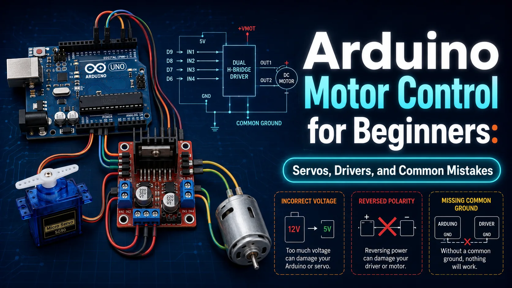
Learn how to safely and effectively control servos, DC motors, and stepper motors with your Arduino, while avoiding the most common beginner mistakes.
Introduction to Arduino Motor Control
The ability to bring physical objects to life is one of the most exciting aspects of working with Arduino and interactive electronics. Whether you are building a self-driving robot, an automated window blind opener, or a robotic arm, understanding how to control motors is a crucial step in transitioning from simple LED projects to dynamic mechanical systems.
However, many beginners face significant hurdles when dealing with motors for the first time. This is rarely due to complex coding; rather, it stems from the fundamental differences between low-power digital circuits and high-power mechanical systems. Success in this area requires a clear understanding of current, voltage, and how to isolate your microcontroller from electrical noise.
In this practical guide, we will explore the three main types of motors you will encounter in your DIY journey: servo motors, DC motors, and stepper motors. We will cover how each type works, how to select the appropriate motor driver, and most importantly, how to avoid the common mistakes that can lead to damaged components.
Understanding Servos: Precision and Simplicity
If your project requires precise angular movement without complex circuitry, a standard servo motor is your best choice. Unlike standard DC motors that spin continuously, a typical servo motor allows you to command it to go to a specific angle, usually between 0 and 180 degrees. This makes them ideal for steering mechanisms, robotic joints, or latch systems.
Inside a servo motor, you will find a small DC motor, a set of gears to reduce speed and increase torque, a potentiometer for position feedback, and an integrated control circuit. This internal control board is what makes servos incredibly easy to use with Arduino; it interprets a Pulse Width Modulation (PWM) signal from the microcontroller and translates it directly into physical position.
To connect a small servo (like the popular SG90) to an Arduino, you only need three wires: Ground (GND, usually black or brown), Power (VCC, red), and Signal (yellow or orange). By utilizing the built-in 'Servo.h' library in the Arduino IDE, you can write a few lines of code to sweep the motor to any position, such as using the command `myservo.write(90)` to center the motor.
DC Motors and the Necessity of Motor Drivers
Standard DC motors are the go-to choice when you need continuous, high-speed rotation, such as for driving wheels on a robot or spinning a cooling fan. These motors have only two terminals; applying direct current to these terminals causes the motor to spin in one direction, while reversing the polarity reverses the direction of rotation.
However, a major pitfall for beginners is attempting to power a DC motor directly from the Arduino's digital pins. Arduino pins can only safely output about 20 to 40 milliamps of current, whereas even a tiny DC motor can draw hundreds of milliamps under load, and several amps when stalled. Connecting a motor directly to an Arduino pin will likely destroy the microcontroller chip.
To bridge this power gap, we use a motor driver. A motor driver acts as an electronic switchboard (often utilizing an H-Bridge circuit) that takes low-current control signals from the Arduino and uses them to switch a high-current external power supply to the motor. Popular driver chips and modules like the L293D or L298N allow you to control both the speed (via PWM) and the direction of the motor safely.
Stepper Motors: The King of Precision
When your project demands continuous rotation combined with absolute precision in positioning and speed, stepper motors are the ultimate solution. These motors are widely used in 3D printers, CNC machines, and camera sliders where exact linear or rotational increments are required.
A stepper motor works by dividing a full 360-degree rotation into a large number of equal steps (for example, 200 steps per revolution, which equals 1.8 degrees per step). By energizing the internal electromagnets in a precise sequence, you can command the motor to rotate by an exact number of steps or hold its position firmly against an external load.
Because controlling multiple coils in sequence is complex, a dedicated stepper driver is essential. Modules like the ULN2003 (often paired with the inexpensive 28BYJ-48 stepper) or the A4988 and DRV8825 are excellent choices. These drivers simplify the process: the Arduino only needs to send a single pulse to the driver to move the motor one step, and a high/low signal to determine the direction.
Crucial Power Rules and Common Mistakes
The most common mistake beginners make is powering motors directly from the Arduino's 5V pin while the board is connected to a computer via USB. While this might work for a tiny, unloaded servo, it will cause the Arduino to reset or fail when a larger load is applied. The golden rule of motor control is: always use an external power supply dedicated to your motors.
Another frequent error is forgetting to establish a common ground. When using an external power supply for your motors and a separate supply (like USB) for your Arduino, you must connect the negative terminal (GND) of the external supply to the GND pin of the Arduino.
Without this common reference point, the control signals will have no return path, leading to erratic motor behavior.
Lastly, many beginners ignore the threat of Back EMF (electromotive force). When a motor stops spinning, it briefly acts as a generator, sending a high-voltage spike back into the circuit. Always ensure your motor driver has built-in flyback diodes, or add them manually to your circuit, to prevent these high-voltage spikes from damaging your sensitive transistors and microcontrollers.
Step-by-Step Checklist for Your First Motor Project
To ensure a safe and successful build, we recommend a methodical step-by-step approach. Start by drawing your wiring diagram on paper or using a simulator like Tinkercad before making any physical connections. Clearly separate your high-current power lines from your low-current signal lines to prevent electrical interference.
When assembling the physical circuit, always connect the ground wires first, followed by the control and signal wires between the Arduino and the driver. Leave the main power lines to the motors as the final step. Double-check all connections for potential short circuits before turning on the power supply.
Finally, start with a very simple test sketch that does nothing more than spin the motor in one direction for a second and then stop. Once you have verified that the mechanical and electrical components are working correctly and safely, you can begin adding complexity to your code, such as reading sensors or implementing speed control.
Comparison table
Motor Type | Control Method | Mechanical Precision | External Driver Required? | Best Use Case |
|---|---|---|---|---|
Servo Motor | PWM / Specific Angle | Very High (within 180-degree range) | No (built-in controller) | Robotic arms, steering mechanisms, locks |
DC Motor | DC Voltage / Speed & Direction | Low (without external encoder) | Yes (H-Bridge required) | Robot wheels, fans, simple toys |
Stepper Motor | Step & Direction Pulses | Extremely High (discrete steps) | Yes (dedicated stepper driver) | 3D printers, CNC machines, precision sliders |
Frequently asked questions
Why does my Arduino reset every time my motor starts spinning?
This happens because the motor draws a large surge of current when starting up, causing a temporary voltage drop (brownout) on the Arduino's power line. To fix this, use a separate external power supply for the motor and place a large capacitor (e.g., 100uF to 470uF) across the motor's power input to smooth out voltage fluctuations.
Can I run a 12V DC motor using a 5V Arduino?
Yes, you can easily do this by using a suitable motor driver like the L298N. You connect the external 12V power supply to the motor driver's power input, and connect the Arduino's 5V control pins to the driver's signal inputs. Remember to connect the Arduino GND to the external power supply's GND.
What is the difference between a standard servo and a continuous rotation servo?
A standard servo moves to and holds a specific angle (usually between 0 and 180 degrees). A continuous rotation servo has been modified to rotate 360 degrees continuously; in this case, the angle command in your code controls the speed and direction of rotation rather than the position.
How do I choose between a stepper motor and a servo motor for my project?
Choose a servo motor if you need simple, high-torque movement within a limited range (like 180 degrees) and want an easy setup. Choose a stepper motor if you need continuous rotation with extremely precise control over position and speed, such as in 3D printers or automated camera rigs.
Comments
Be the first to comment.